Wednesday, April 18, 2018

Fractal Tree in C++ using OpenGL

Following snapshots were obtained in C++ using OpenGL.
I rotated the scene and got different views of the tree.
Snapshots:


Here is the source.

Dynamic Bezier Curve in Java using JOGL

I have named this project as Dynamic Bezier Curve. It uses Evaluators of Bezier curves.

Two bezier curves are joined at the intersection point. The snake winds its way through the 3D path at random. So control points to draw the bezier curve are chosen randomly. These control points are created inside a cube using random number generation.

There are at-least 4 control points needed to draw one Bezier curve.
Two such control point arrays are used here.
They are arranged such that the last point of the first curve and the first point of the second curve are same. Not only that second last and last point of the first curve and first and second point of the second curve are lying on the same line. This is done to ensure continuity and smoothness at the joining point.

Here is a video of the output: https://youtu.be/zmLIoLXHiV8


Here is the source.

Thursday, January 18, 2018

Simple Side Scroller - A Unity Game

Guest Post from Siddhant Gupta

If you have always wanted to create your own game but felt intimidated by game development, this project is a great place to begin. In this tutorial we create a simple side-scrolling shooter in Unity using freely available assets and a few straightforward C# scripts.

By the end of this tutorial, you will have:
• A scrolling background
• A controllable aircraft
• Bullet firing mechanics
• Smooth acceleration and movement
• An understanding of Unity Prefabs and scripting basics

The best part is that every feature can be extended to create your own unique game.

This Simple Side Scroller is a game made from resources mentioned in the site at the end of this post. 
In this game, the player pilots a fighter plane through an endlessly scrolling world while firing bullets at enemies. The project demonstrates how a few simple ideas—scrolling backgrounds, object prefabs and player controls—combine to create an engaging arcade game. 
This is a description of the features of the resources:

Free plane sprite for your side scrolling shooter games

Features:
  • 1 Plane with 3 animations: fly, shoot, & dead
  • Simple background
  • Fully editable vector source files in SVG and AI file formats.
  • Separate PNG sequence files for quick integration in your game projects
Here is how you set up the background image:


You may consult YouTube videos on how to change background.
Create a big Background Quad and apply a texture to it like this.
Change the background sprite to repeat (default is clamp) and hit the Apply button. 
This will allow our background to scroll freely without any artifacts. You may not perceive it but our plane will be stationery and the background will move up and down.
Now click and drag the BG sprite/texture to the Quad, the quad will be UV wrapped by this texture now.
At first the texture will appear very dark, because it is a Standard Shader with an Albedo texture so it interacts with all the lights in the world, since this is a simple 2D game we wont be interacting with lights, so we have to change the texture to an Unlit shader which supports a texture.
Browse to the mesh Renderer of the Quad and click on the Shader Dropdown and select Unlit/Texture. Now u have a properly lit textured quad, doesn't Unity make such complex things so simple! 😃


It is always a good idea to rename our objects in the scene to something that makes sense , so we will rename our Quad to Background (name it to whatever u want).

Now Comes the Fun Part – Coding the Scrolling Background

So first lets make out background scroll to give the fake illusion of player moving
Create a new Script , called Scroller.cs.


````
using System.Collections;
using System.Collections.Generic;
using UnityEngine;

public class Scroller : MonoBehaviour {
//Public field shows up in the inspector so it can be easily 
//tweaked even while the game is 
//running
public float scrollSpeed;
//Private fields dont show up in the inspector
private float scrollValue;
private MeshRenderer renderer;
// Use this for initialization
void Start () {
renderer = GetComponent<MeshRenderer>();
}
// Update is called once per frame

void Update () {
// Update the scroll value .....Time.deltaTime is used to make sure the 

// scrolling is independent of the fps the game is running on.
scrollValue += scrollSpeed*Time.deltaTime;
// UV values range from 0 - 1 so there is no point in exceeding the 
// value > 1 , so we reset the value back to 0 , in order to loop it.

if(scrollValue >= 1f)
{
scrollValue = 0f;
}
//Update the Main texture offset X value to make it scroll horizontally.
renderer.material.mainTextureOffset = new Vector2(scrollValue,0f);
}
}

````

Challenge yourself: Try changing the value of scrollSpeed and observe how the feel of the game changes. Small modifications like this are one of the best ways to learn Unity.

The idea of this script is to update the UV Offset of the Main Texture (Background texture) of the quad. This will allow us to scroll it in real time.

Time.Delta time is very important to make Your calculations independent of frames per second, I would suggest u too try this code without Time.deltaTime (Comment that out) and see
What happens?
(Spoiler : The scrollValue in Scroller.cs will take unpredictable jumps which will cause the bg to scroll unevenly.)

Q. What is Awake()?
A. Unity invokes the Awake method on all the gameObjects active in the scene when the scene starts.

Q. What is Start()?
A. After Awake, Start method is called, so these two methods can be used as constructors for our objects and classes, all the initial requirements of the code can be put here, like assigning references or grabbing the MeshRenderer component like we did in the Scroller.cs script, because before we can use the component in the code, we need a reference to it. The Mesh Renderer component can be grabbed in Awake() or Start() , it wont make a difference in this example as the first use of the renderer is in the update script.

Q What is Update()?
A This is the main method , which u will end up using a lot , basically Unity calls this method each frame, so all the code under this method will get Updated each frame. Anything that requires to be run/executed each frame should be done inside this method.

It has all the details u need to know about Unity's Script Execution order

Ok so we r done with bg scrolling now lets move on to the player movement and firing bullets
Before we move on to scripting, lets talk about Unity Prefabs.


Prefabs are a great way to change multiple instances of the same GameObject from only a single object called prefab. Imagine if u have 10 point lights in the scene now u want to change their color from say yellow to red, instead of clicking each and every light and changing its property, what u can do is drag and drop one point light from the scene to the asset folder(we have created a prefab folder under assets, I urge u to do the same, keeps our hierarchy clean) to create a prefab of that object, now u can drag this prefab and put it in the scene multiple times. So now say we have 10 Point lights in the scene which are clones of that prefab, but the good thing is now if u change the color of the prefab to red then all the clones of that prefab in the scene will also change to red color.
Isn't that amazing how Unity simplifies small things, that make a huge difference in the development process.
Here is a much better explanation of Prefabs than I could give, please refer to this link before proceeding from Here.
Prefabs are one of Unity's most powerful productivity features. Learn them early and they will save you countless hours as your projects become larger.

````
using System.Collections;

using System.Collections.Generic;
using UnityEngine;

public class Player : MonoBehaviour
{
    public float accel = 0f;
    public float currentSpeed;
    public float targetSpeed;
    public float fireDelay = 0f;

    private float timeElapsed = 0f;
    public GameObject bulletPrefab;

    // Use this for initialization
    void Start()
    {
    }

    // Update is called once per frame
    void Update()
    {
        //Detect Keyboard Input
        if (Input.GetKey(KeyCode.S))
        {
            targetSpeed = -5f;
        }
        else if (Input.GetKey(KeyCode.W))
        {
            targetSpeed = 5f;
        }
        else
        {
            targetSpeed = 0f;
        }

      //Lerp the CurrentSpeed towards the targetSpeed
        MoveToTargetSpeed();
        if (Input.GetKey(KeyCode.Space))
        {

/* ADD a delay between each time the player fires the bullet , so we dont spam the frame with multiple bullet objects , usually 0.1s dealy works good
but it all depends on ur game design and difficulty.This variable can also be used as an upgrade option , where the players can change their ships firing speed.*/
           
            timeElapsed += Time.deltaTime;
            if (timeElapsed >= fireDelay)
            {
                Fire();
                timeElapsed = 0f;
            }
        }
    }
    void MoveToTargetSpeed()

    {
        /* Increment or Decrement the currentSpeed value  */
   currentSpeed += accel * Time.deltaTime * Mathf.Sign(targetSpeed - currentSpeed);

/* This is where the bug happens but it is a nice feature to have so i kept this poor piece of logic */
        if (Mathf.Abs(Mathf.Abs(targetSpeed) - Mathf.Abs(currentSpeed)) < 0.01f)
        {
            currentSpeed = targetSpeed;
        }

/* Store the Next Position to update in temp var so that we can check if the player is reaching the bonds of the device's screen you dont want the player to go off the screen. Camera.main.WorldToScreenPoint is a helpful method to convert any Vector in world space to screen space. We need the player Coordinates in screen space so we can compare it to the device height and width which are pixel values  */


Vector3 nextPos = new Vector3(transform.position.x, transform.position.y + currentSpeed * Time.deltaTime, transform.position.z);
        if (Camera.main.WorldToScreenPoint(nextPos).y > Screen.height || Camera.main.WorldToScreenPoint(nextPos).y < 0f)
        {

/* if players next position is crossing the device's screen bounds then stop the movement and return to Update , this skips the actual position update we r doing in the last line of this method*/
            currentSpeed = 0f;
            targetSpeed = 0f;
return;
        }
// if everything is alright then update the player position.
         transform.position = nextPos;
    }

    void Fire()
    {

// Create a clone of the Bullet GameObject at the current player position and the // bullets 
// rotation should be the default prefab rotation.
        Instantiate(bulletPrefab, transform.position, Quaternion.identity);
    }
}
````

The above player script is pretty straightforward, check for inputs, set targetSpeed accordingly and lerp the current speed towards the target speed to get a feeling of acceleration.

The player script holds a reference to a prefab called BulletPrefab, so we can change and modify the bullets from one single object.

The script also allows the player ship to Fire after a delay of 0.1s. It is good to have a delay so as not to spam the frame with multiple bullets(that is just unrealistic and would probably lag out your system).
Now there is a fun part to this code, which I did not realize while writing, 
I produced a bug in the movement code but decided to keep it as a feature 😜. 

One of the most interesting things happened accidentally. A tiny imperfection in the movement logic caused the plane to drift slightly up and down. Instead of removing it immediately, I kept it because it gave the aircraft a subtle turbulence effect, making the movement feel more natural.

Sometimes, bugs become features!

If you notice the player ship keeps floating up and down randomly that's because the currentSpeed variable in the Player.cs never actually sets to 0, it will give a +- 1f fluctuation. It makes the player ship move more realistically cause no plane flies in a perfect straight line, winds cause the plane to have a little turbulence which is showed here by the random up and down movement, isn't that cool !!!

To make the bullets move when fired a simple Bullet.cs script is used

````
using System;
using System.Collections.Generic;
using UnityEngine;

public class Bullet : MonoBehaviour
{
    public float speed;

    void Update()


    {
        transform.Translate(new Vector3(speed,0f,0f)*Time.deltaTime);
    }
}
````

Nothing much to explain here, when the bullets are instantiated by the player, the Update() method of the bullet script starts getting invoked which translates the bullet in forward direction. Refer to the code comments for better details.

Just a few lines of Code and we already have soo much going on.

Final Thoughts

This project shows that game development is not about writing thousands of lines of code. With a few sprites, a scrolling background, prefabs and simple scripts, you can already create a playable game.

If you are a student learning Unity, I encourage you to modify this project:

  • Add enemies

  • Add explosions and sound effects

  • Implement a score system

  • Introduce multiple levels

  • Design your own aircraft

Every successful game begins with a small experiment. This side scroller could be yours.


Sources:


Tuesday, December 5, 2017

Simple Wavefront .OBJ Model Loader in JOGL

Wavefront .OBJ files are the most simplest of models that can be loaded into OpenGL. I have loaded some simple files and it has worked well. Im still working on other files containing negative vertex indexes.

This is an image of an elephant and a college visualized in a model mentioned in this site=> http://netization.blogspot.in/2014/10/loading-obj-files-in-opengl.html

On request I have texture mapped a custom texture to the elephant body(Chess board pattern)


If you are interested in the .OBJ model file format it is a simple text based model. It does not use any compression in storing the vertices or their relations. Hence this file format is human readable to some extent and editable to a fair degree of control. I am reproducing some text describing the format from an E-Book by David J Eck(without permission of course).
Wavefront .OBJ file format:
For complex shapes that are not described by any simple mathematical formula, it’s not feasible to generate the shape using Java code. We need a way to import shape data into our programs from other sources. The data might be generated by physical measurement, for example, or by an interactive 3D modeling program such as Blender (http://www.blender.org). To make this possible, one program must write data in a format that can be read by another program. The two programs need to use the same graphics file format. One of the most common file formats for the exchange of polygonal mesh data is the Wavefront OBJ file format. Although the official file format can store other types of geometric data, such as Bezier curves, it is mostly used for polygons, and that’s the only use that we will consider here.
An OBJ file (with file extension “.obj”) can store the data for an indexed face set, plus normal vectors and texture coordinates for each vertex. The data is stored as plain, human-readable text, using a simple format. Lines that begin with “v”, “vn”, “vt”, or “f”, followed by a space, contain data for one vertex, one normal vector, one set of texture coordinates, or one face, respectively. For our purposes here, other lines can be ignored. A line that specifies a vertex has the form
v x y z
where x, y, and z are numeric constants giving the coordinates of the vertex. For example:
v 0.707 -0.707 1
Four numbers, specifying homogeneous coordinates, are also legal but, I believe, rarely used. All the “v” lines in the file are considered to be part of one big list of vertices, and the vertices are assigned indices based on their position in the list. The indices start at one not zero, so vertex 1 is the vertex specified by the first “v” line in the file, vertex 2 is specified by the second “v” line, and so on. Note that there can be other types of lines interspersed among the “v” lines—those extra lines are not counted when computing the index of a vertex.
Lines starting with “vn” or “vt” work very similarly. Each “vn” line specifies a normal vector, given by three numbers. Normal vectors are not required to be unit vectors. All the “vn” lines in the file are considered to be part of one list of normal vectors, and normal vectors are assigned indices based on their order in the list. A “vt” line defines texture coordinates with one, two, or three numbers. (Two numbers would be used for 2D image textures.) All the “vt” lines in the file create a list of texture coordinates, which can be referenced by their indices in the list.
Faces are more complicated. Each “f” line defines one face, that is, one polygon. The data on the “f” line must give the list of vertices for the face. The data can also assign a normal vector and texture coordinates to each vertex. Vertices, texture coordinates, and normals are referred to by giving their indices in the respective lists. (Remember that the numbering starts from one, not from zero; if you’ve stored the data in Java arrays, you have to subtract 1 from the numbers given in the “f” line to get the correct array indices. There reference numbers can be negative. A negative index in an “f” line means to count backwards from the position of the “f” line in the file. For example, a vertex index of −1 refers to the “v” line that was seen most recently in the file, before encountering the “f” line; a vertex index of −2 refers the “v” line that precedes that one, an so on. If you are reading the file sequentially and storing data in arrays as you go, then −1 simply refers to the last item that is currently in the array, −2 refers to the next-to-last item, and so on.)
In the simple case, where there are no normals or texture coordinates, an “f” line can simply list the vertex indices in order. For example, an OBJ file for the pyramid example from the previous subsection could look like this:
v 1 0 1
v 1 0 -1
v -1 0 -1
v -1 0 1
v 0 1 0
f 5 4 1
f 5 1 2
f 5 2 3
f 5 3 4
f 1 4 3 2
When texture coordinate or normal data is included, a single vertex index such as “5” is replaced by a data element in the format v/t /n, where v is a vertex index, t is a texture coordinates index, and n is a normal coordinate index. The texture coordinates index can be left out, but the two slash characters must still be there. For example, “5/3/7” specifies vertex number 5, with texture coordinates number 3, and normal vector number 7. And “2//1” specifies vertex 2 with normal vector 7. As an example, here is complete OBJ file representing a cube, with its normal vectors, exactly as exported from Blender. Note that it contains additional data lines, which we want to ignore:
# Blender3D v248 OBJ File:
# www.blender3d.org
mtllib stage.mtl
v 1.000000 -1.000000 -1.000000
v 1.000000 -1.000000 1.000000
v -1.000000 -1.000000 1.000000
v -1.000000 -1.000000 -1.000000
v 1.000000 1.000000 -1.000000
v 0.999999 1.000000 1.000001
v -1.000000 1.000000 1.000000
v -1.000000 1.000000 -1.000000
vn -0.000000 -1.000000 0.000000
vn 0.000000 1.000000 -0.000000
vn 1.000000 0.000000 0.000000
vn -0.000000 -0.000000 1.000000
vn -1.000000 -0.000000 -0.000000
vn 0.000000 0.000000 -1.000000
usemtl Material
s off
f 1//1 2//1 3//1 4//1
f 5//2 8//2 7//2 6//2
f 1//3 5//3 6//3 2//3
f 2//4 6//4 7//4 3//4
f 3//5 7//5 8//5 4//5
f 5//6 1//6 4//6 8//6

Once you have read a geometric object from an OBJ file and stored the data in arrays, it is easy enough to use the arrays to draw the object with OpenGL.

Monday, December 4, 2017

Object Model Loader in OpenGL

The example provided here at this site was the most simplest of all loaders that I could find on the Internet. I am now trying to load Wavefront .obj files created in Blender in C++ OpenGL.

Here are the snaps of the few objects loaded...
In reverse order
Elephant
College
Porsche
Radar
Teddy


You can download the source and obj files from the site mentioned.
Things that you can do with these files is you can group vertices into faces and faces into components which you can transform and animate in 3D. For example you can load the model created in Blender exported as OBJ file into OpenGL and then display them the way you want.

I have implemented some of the tasks mentioned above a post in this next post: >>>>>> Click Here <<<<<< to visit.


Tuesday, November 28, 2017

Mandelbrot and Julia Set in OpenGL

I have ported the C code from an earlier project to OpenGL. This code runs much faster with better compiler than the earlier runtime environment of TurboC++.
You have to click on certain regions of the Mandelbrot Set and get the Julia Set.

Snapshots:


After clicking a point in the above diagram we get this image below:
(Hint: Those regions that are at the boundary of the Mandelbrot set have got richer Julia set patterns, hence clicking on anywhere and everywhere will not get you interesting patterns)


Here is the source.

This e-book is a really good source of reference for the theory behind this....

Chaos
It has the following chapters:

Iteration
Bifurcation
Universality
Strange Attractors
Strange and Complex
Julia Sets
Mandelbrot Sets
About Dimension
Euclidean Dimension
Topological Dimension
Fractal Dimension
Measuring Chaos
Harmonic Oscillator
Logistic Equation
Lyapunov Exponent
Lyapunov Space
~~~~~~~~~~~~~~~~~~~~~~~~~~~~~~~~~~~~~~~~~~~~
In JOGL the same thing implemented using Modern OpenGL published in the site:
https://blog.nobel-joergensen.com/

Snapshot:

Here is a link to the Source into my Github.

Wednesday, November 22, 2017

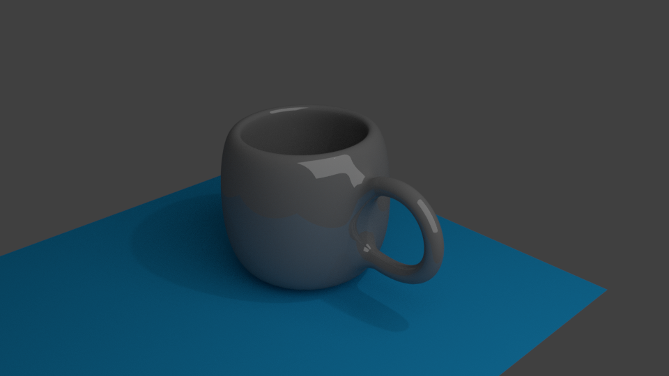
Blender Cup

I have followed a tutorial on making a cup in blender to make well, a cup. Here are two views of the final rendered cup.


This is the link to the video I followed and I recommend people to try making this at leisure.
https://www.youtube.com/watch?v=y__uzGKmxt8
The experience is exhilarating!
After yesterday's adventure I set out to repeat the exercise today again. After several blunders and having many re-looks at the video I generated the following cup(remade from a different view and resolution)

Following this I have made cloth simulation and generated the following image at resolution of 2000.